DIY Dry box — Part 9
The software is ready and the test hardware works. Time to assemble everything.
Putting sensors in dryboxes
That’s one of the easy parts:
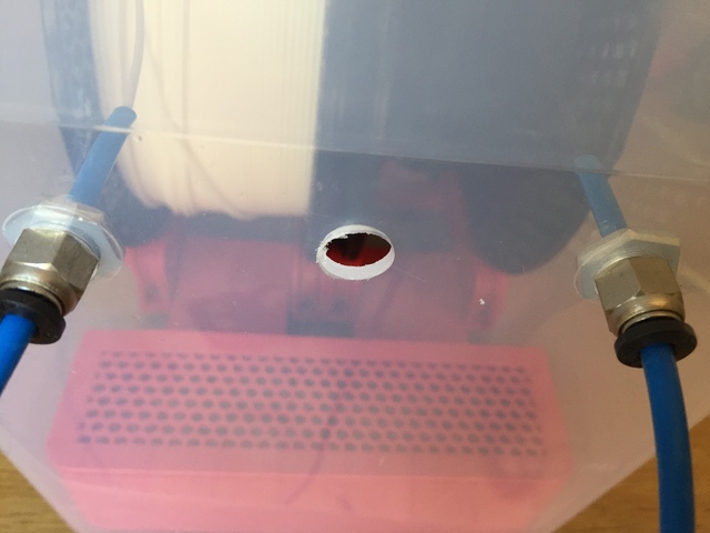
- drill a hole in the drybox;
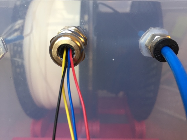
- screw in a waterproof cable gland;
- pass the cables through;
- tighten the cable gland to make it airtight;
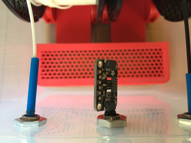
- connect the sensor.
Soldering
I’m not going to show it, it’s too ugly, but I did learn new technics to slightly improve my soldering skills.
Let’s put a sensor in a drybox and plug it to the board:
And the result in Gladys Assistant:
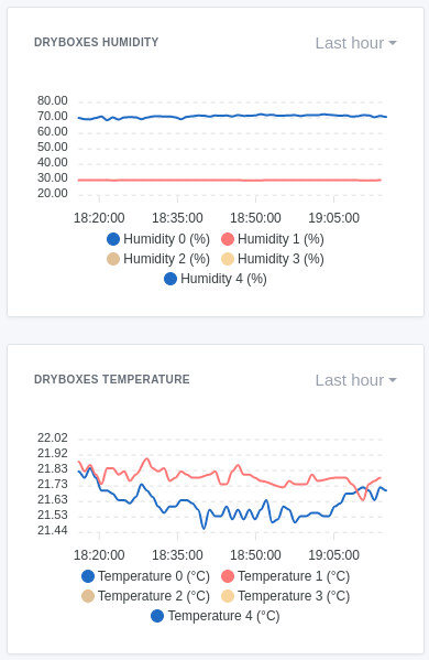
So 70 % humidity outside the drybox, 30 % inside, and temperature of 21,7 °C inside and outside the drybox. Sounds good.
Cables
In the previous test, the sensor was next to the microcontroller. The issue is that the boxes are going to be much further away than that. Between the microcontroller and the farthest drybox will be about 1 meter.
I don’t have I²C cables that long. And there’s a reason for that. It’s not meant for “long” distances. The longest ones I have seen were 30 or 40 centimeters long.
The issue is that cables are not perfect and have resistance and inductance, reducing the signal strength and making the digital signal less “square”.
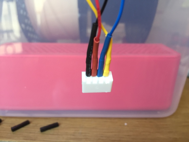
Having old ethernet cables with broken connectors, I decided to try to use one. Why? The cables I’m using are F/UTP (foiled/unshielded twisted pair), so there’s 4 pairs, each pair is 2 cables twisted together preventing crosstalk. And there’s a foil around the whole cable preventing electromagnetic interferences.
That should do the trick… and it does… after spending hours attaching connectors (another thing I improved my skills on during that project).
Box for the microcontroller
I quickly did a protection box for the microcontroller to make it easier to handle.
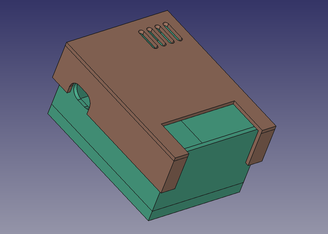
Assembly
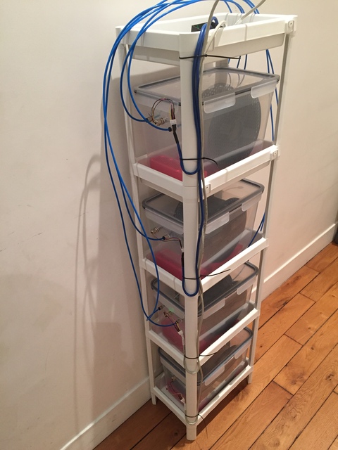
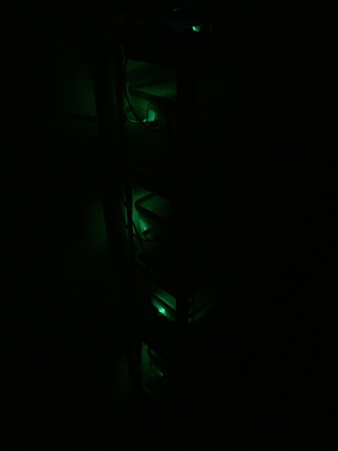
Now putting everything together… shame I can't turn off the green LEDs on the sensor boards:
Now all boxes are sending their data. After using it for a while, I find interesting that the temperature lines are parallel to each other, the box at the top being the hottest one and the one at the bottom being the coldest one. Also, now I have humidity between 10 and 17 %… so the boxes are doing their job.

Power consumption
The HTU31D sensors consumes about 2 mW when measuring, so 10 mW for the 5 sensors. The TCA9548A multiplexer seems to consume about 0,3 mW. The ESP32-C3 consumes a maximum of 1,1 W (if I read the datasheet properly).
So the microcontroller is by far the component that can consume the most, and that’s because of the Wi-Fi/BLE part. But I don’t think this will reach the maximum consumption, also most of the time the microcontroller will be sleeping. Best solution, as always, is to measure:
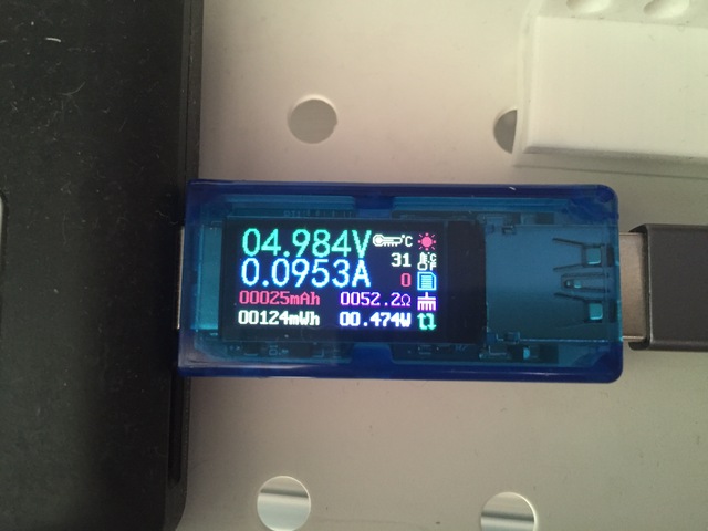
Measured power consumption:
- 474 mW while measuring, this step lasts less than 5 seconds;
- 13 mW while sleeping, this step lasts 60 seconds.
After 4 hours, it had consumed 130 mWh, so the average power consumption is 32,5 mW.
I’m keeping it that way for now, but at some point I will reduce to measure humidity and temperature only every 30 minutes or every hour, hence reducing the power consumption. I don’t need to have a value every minute, the idea is to be able to follow the evolution of humidity on a longer timeframe to see when the dessicant needs to be replaced.
That’s all for this series of posts.

